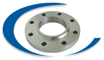
Slip On Flange
What is Slip-on Flange?

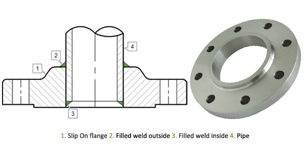
Slip-on pipe flange usually slips over the pipe. Slip-on pipe flanges are typically made with an inside diameter of the pipe flange slightly larger than the outside diameter of the pipe. This allows the slip-on flange to slip over the pipe. Slip-on pipe flanges are welded (usually both inside and outside) to provide strength and prevent leakage. Slip-on pipe flanges can sometimes also have a boss/ring or hub, and can be made with a bore to suit either pipe or tube. Ring pipe flanges and hub pipe flanges are both considered slip-on pipe flanges because they both slip over the pipe.
Slip-on flanges are generally preferred by users over weld neck flanges, as they are a cheaper option than weld neck flange and the fact that less accuracy is required when cutting pipe to length.Slip-on flanges are available with raised, flat or RTJ faces, and are also available in orifice configurations.We offer slip-on pipe flanges manufactured at our facility to companies in various industries including shipbuilding, power generation, petrochemical plants, oil refineries, waste water treatment plants, paper mills, pharmaceutical plants and turnkey projects among others.We are an ISO 9001:2008,ISO 9001-2008, ISO 14001-2004, OHSAS 18001-2007, NSIC-CRISIL, EEPC, and QA-UKAS (ISO 9001-2008), SSI Certified company that follows total Quality Management System. and have been recognized as one of the world’s leading stockists and manufacturer of quality metals for over two decades and are committed to quick responses, unsurpassed quality, competitive pricing, reliable deliveries and an exhaustive inventory.
Slip-on Flanges Specification
| Type | Slip On Flanges |
| Standards | ANSI B16.5, ANSI B16.47 Series A & B, MSS SP44, ASA, API-605, AWWA, Custom Drawings |
| Outside Diameter | ≤ 24 = 1.6 mm > 24 = ± 3.2 mm |
| Inside Diameter | ≤ 10 = ± 0.8 mm > 12 = + 1.6 mm / - 0 mm |
| Diameter Contact Face | 1.6 mm RF = ±0.8 mm 6.35 mm RF = ±0.4 mm Tongue & Groove = ±0.4 mm Male-Female = ±0.4 mm |
| Outside Diameter of Hub | ≤12 = + 2.4 mm/ - 1.6 mm ≥ 14 = ± 3.2 mm |
| Diameter of Counterbore | Same as for Inside Diameter |
| Drilling | Bolt Circle = 1.6 mm Bolt Hole Spacing = ±0.8 mm Eccentricity Bolt Circle with Respect to Facing ≤2.1/2 = 0.8 mm max ≥3 = 1.6 mm max |
| Thickness | ≤18 = +3.2 mm / -0 ≥20 = +4.8 mm / -0 |
| Length thru Hub | ≤18 = 3.2 mm / - 0.8 mm ≥20 = + 4.8 mm / - 1.6 mm |
| Pressure Ratings: | Class 150, Class 300, Class 400, Class 600, Class 900, Class1500, Class 2500 | PN6, PN10, PN16, PN25, PN40, PN64 etc. |
| Order | Accept custom order |
| Quality Assurance | All fittings and flanges are subject to strict inspection at each stage of the production process, from starting material purchasing to product dispatch. They are visually examined for conformity to ASTM, ASME, MSS, DIN, EN, and JIS codes and standards. Upon request, official certified Inspection Agencies can be called in to witness the material reports, dimensions and quality conformity of products. |
| Marking & Packing | Products are packaged to ensure that there is no damage during transit. In case of exports, standard export packaging is done in wooden cases. All buttweld fittings are marked with Grade, Lot No, Size, Degree and our trade mark. On special requests we can also, make custom marking on our products.#Protected by End Caps. |
| Value Added Services |
|
| Test Certificates | Manufacturer Test Certificate as per EN 10204 / 3.1B, Raw Materials Certificate, 100% Radiography Test Report, Third Party Inspection Report |

The calculated strength from a Slip On flange under internal pressure is of the order of two-thirds that of Welding Neck flanges, and their life under fatigue is about one-third that of the latter. The connection with the pipe is done with 2 fillet welds, as well at the outside as also at the inside of the flange.
The X measure on the image, are approximately:
Wall thickness of pipe + 3 mm.
This space is necessary, to do not damage the flange face, during the welding process. A disadvantage of the flange is, that principle always firstly a pipe must be welded and then just a fitting. A combination of flange and elbow or flange and tee is not possible, because named fittings have not a straight end, that complete slid in the Slip on flange.
| Carbon Steel Lap Joint Flanges: | ASTM A105/A105N, A350 LF1, LF2 CL1/CL2, LF3 CL1/CL2, A694 F42, F46, F48, F50, F52, F56, F60, F65, F70, A516.60, 65, 70 (Spectacle Blind Flange, Spacer Ring/Spade Flange), Steel RST37.2, C22.8 |
| Stainless Steel Lap Joint Flanges: | ASTM A182 F202, F304/304L/304H, F316/316L, F316H, F316TI, F310, F321, F904L |
| Alloy Steel Lap Joint Flanges: | ASTM A182 F1, F5, F9, F11, F22, F91 |
| Special Alloy Lap Joint Flanges: | Duplex, Super Duplex, Nickel Alloys |
| Flange Face Type: | Weld neck Flate Face (WNFF), Weld neck Raised Face (WNRF), Weld neck Ring Type Joint (WNRTJ) |
| Coating/Surface Treatment: | Anti-rust Paint, Oil Black Paint, Yellow Transparent, Zinc Plated, Cold and Hot Dip Galvanized |
