Socket Weld Flange
What is Socket weld Flange?

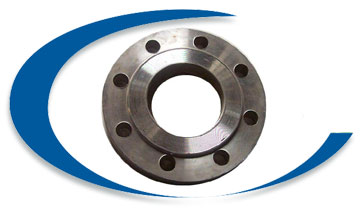
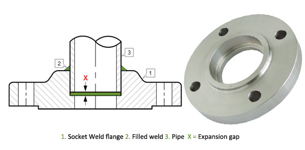
Socket weld flange is similar to the slip-on flange in outline, but the bore is counter-bored to accept pipe. Socket welding pipe flanges are typically used on smaller sizes of high pressure pipes. Socket weld flanges are widely used in high pressure systems such as hydraulic equipment and steam lines. Socket weld pipe flanges are attached by inserting the pipe into the socket end and then applying fillet weld around the hub of the flange. This allows for a smooth bore and better flow of the fluid or gas inside of the pipe. An optional internal weld may be applied in high stress applications.
We offer socket welding flanges manufactured at our facility to companies in various industries including shipbuilding, power generation, petrochemical plants, oil refineries, waste water treatment plants, paper mills, pharmaceutical plants and turnkey projects among others.We are an ISO 9001:2008,ISO 9001-2008, ISO 14001-2004, OHSAS 18001-2007, NSIC-CRISIL, EEPC, and QA-UKAS (ISO 9001-2008), SSI Certified company that follows total Quality Management System. and have been recognized as one of the world’s leading stockists and manufacturer of quality metals for over two decades and are committed to quick responses, unsurpassed quality, competitive pricing, reliable deliveries and an exhaustive inventory.
Socket Weld Flange Specification
| Type | Socket Weld Flange |
| Standards | ANSI B16.5, ANSI B16.47 Series A & B, MSS SP44, ASA, API-605, AWWA, Custom Drawings |
| Outside Diameter | ≤ 24 = 1.6 mm > 24 = ± 3.2 mm |
| Inside Diameter | ≤ 10 = ± 0.8 mm > 12 = + 1.6 mm / - 0 mm |
| Diameter Contact Face | 1.6 mm RF = ±0.8 mm 6.35 mm RF = ±0.4 mm Tongue & Groove = ±0.4 mm Male-Female = ±0.4 mm |
| Outside Diameter of Hub | ≤12 = + 2.4 mm/ - 1.6 mm ≥ 14 = ± 3.2 mm |
| Diameter of Counterbore | Same as for Inside Diameter |
| Drilling | Bolt Circle = 1.6 mm Bolt Hole Spacing = ±0.8 mm Eccentricity Bolt Circle with Respect to Facing ≤2.1/2 = 0.8 mm max ≥3 = 1.6 mm max |
| Thickness | ≤18 = +3.2 mm / -0 ≥20 = +4.8 mm / -0 |
| Length thru Hub | ≤18 = 3.2 mm / - 0.8 mm ≥20 = + 4.8 mm / - 1.6 mm |
| Pressure Ratings: | Class 150, Class 300, Class 400, Class 600, Class 900, Class1500, Class 2500 | PN6, PN10, PN16, PN25, PN40, PN64 etc. |
| Order | Accept custom order |
| Quality Assurance | All fittings and flanges are subject to strict inspection at each stage of the production process, from starting material purchasing to product dispatch. They are visually examined for conformity to ASTM, ASME, MSS, DIN, EN, and JIS codes and standards. Upon request, official certified Inspection Agencies can be called in to witness the material reports, dimensions and quality conformity of products. |
| Marking & Packing | Products are packaged to ensure that there is no damage during transit. In case of exports, standard export packaging is done in wooden cases. All buttweld fittings are marked with Grade, Lot No, Size, Degree and our trade mark. On special requests we can also, make custom marking on our products.#Protected by End Caps. |
| Value Added Services |
|
| Test Certificates | Manufacturer Test Certificate as per EN 10204 / 3.1B, Raw Materials Certificate, 100% Radiography Test Report, Third Party Inspection Report |

Socket Weld flanges were initially developed for use on small-size high pressure piping. Their static strength is equal to Slip On flanges, but their fatigue strength 50% greater than double-welded Slip On flanges. The connection with the pipe is done with 1 fillet weld, at the outside of the flange. But before welding, a space must be created between flange or fitting and pipe.
ASME B31.1 1998 127.3 Preparation for Welding (E) Socket Weld Assembly says:
In assembly of the joint before welding, the pipe or tube shall be inserted into the socket to the maximum depth and then withdrawn approximately 1/16" (1.6 mm) away from contact between the end of the pipe and the shoulder of the socket.
The purpose for the bottoming clearance in a Socket Weld is usually to reduce the residual stress at the root of the weld that could occur during solidification of the weld metal. The image shows you the X measure for the expansion gap. The disadvantage of this flange is right the gap, that must be made. By corrosive products, and mainly in stainless steel pipe systems, the crack between pipe and flange can give corrosion problems. In some processes this flange is also not allowed. I am not an expert in this matter, but on the internet, you will find a lot of information about forms of corrosion. Also for this flange counts, that principle always firstly a pipe must be welded and then just a fitting.
| Carbon Steel Lap Joint Flanges: | ASTM A105/A105N, A350 LF1, LF2 CL1/CL2, LF3 CL1/CL2, A694 F42, F46, F48, F50, F52, F56, F60, F65, F70, A516.60, 65, 70 (Spectacle Blind Flange, Spacer Ring/Spade Flange), Steel RST37.2, C22.8 |
| Stainless Steel Lap Joint Flanges: | ASTM A182 F202, F304/304L/304H, F316/316L, F316H, F316TI, F310, F321, F904L |
| Alloy Steel Lap Joint Flanges: | ASTM A182 F1, F5, F9, F11, F22, F91 |
| Special Alloy Lap Joint Flanges: | Duplex, Super Duplex, Nickel Alloys |
| Flange Face Type: | Weld neck Flate Face (WNFF), Weld neck Raised Face (WNRF), Weld neck Ring Type Joint (WNRTJ) |
| Coating/Surface Treatment: | Anti-rust Paint, Oil Black Paint, Yellow Transparent, Zinc Plated, Cold and Hot Dip Galvanized |
